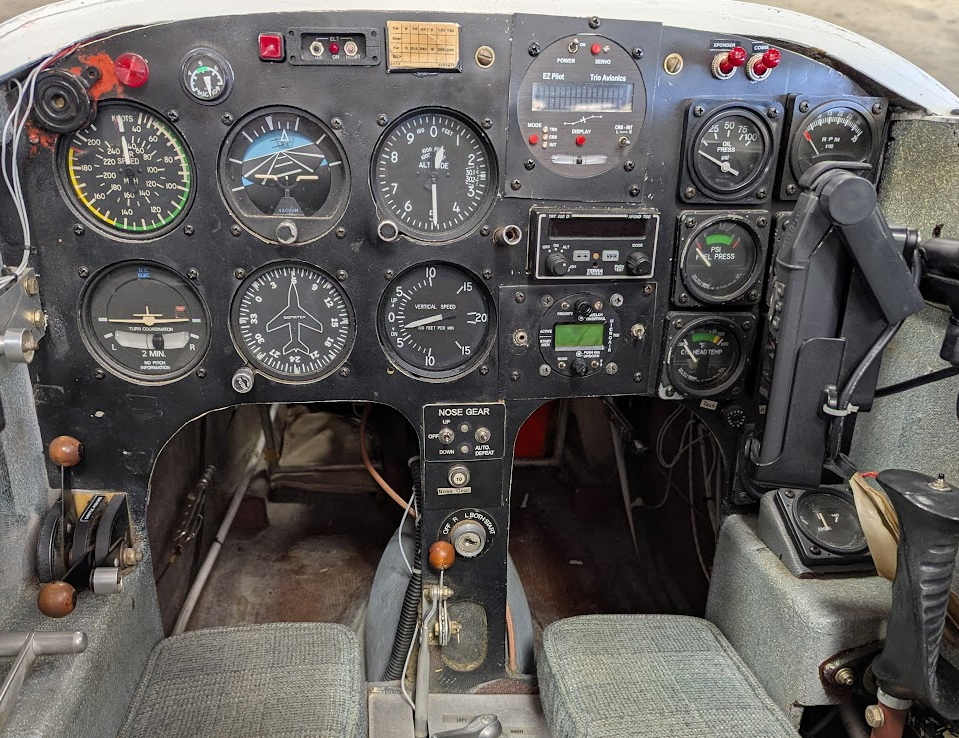
It took a bit longer than I had hoped, but my airplane’s panel upgrades are finally coming to an end. In my previous post, I talked a little about my panel upgrade project, but now that I’ve finally completed the majority of the work, I’d like to dive a bit more into the whole process and what it took to bring to fruition.
When I bought my plane, I always had the intention to do a complete electrical and panel overhaul. Avionics, in my opinion, are one of the more personal choices an aircraft owner can make when deciding what they want to fly behind. We interact with our avionics constantly throughout a flight, and so it makes sense that everyone has an idea of what they like and don’t like. I got my pilot’s license flying very nice SR20s and SR22s, and from there on I’ve always been biased towards glass cockpits and all the information they can provide.
I had initially planned to fly my airplane around with its existing panel for at least a few months. The thinking here was that it’d be better to build time in the type and enjoy the plane a while rather than immediately undergoing a long panel project (also to let my wallet recover a little bit from the initial purchase). However, I ended up proceeding with the upgrades a bit sooner than expected for a few reasons.
There were really three motivating factors. Perhaps the most important one was that I really needed to update for ADS-B compliance. The Terra TRT 250 D transponder provided me mode C (altitude reporting) capabilities, but it didn’t meet the requirements of ADS-B out (automatic self position reporting) necessary for flying in many airspaces. Unfortunately for me, all the local airports where I can base my plane out of fall under the bravo ADS-B veil, and so I had to request a waiver each time I wanted to fly. Not only are you not really supposed to do this regularly, but it was also inconvenient and led to me using it as an excuse to to not fly a couple times.
The second big factor is that I like technology and advanced avionics. In particular, having an engine monitor is something I consider essential, both for the safety of monitoring my engine during a flight, and also for the long term tracking of my engine’s health. Having other capabilities like integrated flight planning, GPS, and checklists are also very nice features of modern avionics equipment.
However, I was willing to deal with no ADS-B and simple steam gauges for a least a little bit, even if it wasn’t ideal. The final nail in the coffin that lead to me springing for the upgrade a little sooner than planned ended up being a couple electrical issues. During one flight, I lost my alternator and my tachometer. After troubleshooting the systems, the tachometer seemed to just be a case of a bad gauge, and the alternator issue ended up being a couple bad crimps on the field wire. While I was able to get the alternator fixed up and working again, I was not content to fly without my tachometer, and the alternator troubleshooting exposed some other electrical issues I really wanted to get fixed up.
So finally I decided it was best to just get going with the panel and electrical overhaul. At this point I had already pretty much finished up my wire harness, and I was just waiting for some hangar space I could use to store my plane while I worked on the upgrades. Fortunately, one of the local avionics shops had some space that was available and offered to let me move in for a bit.
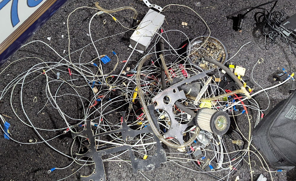
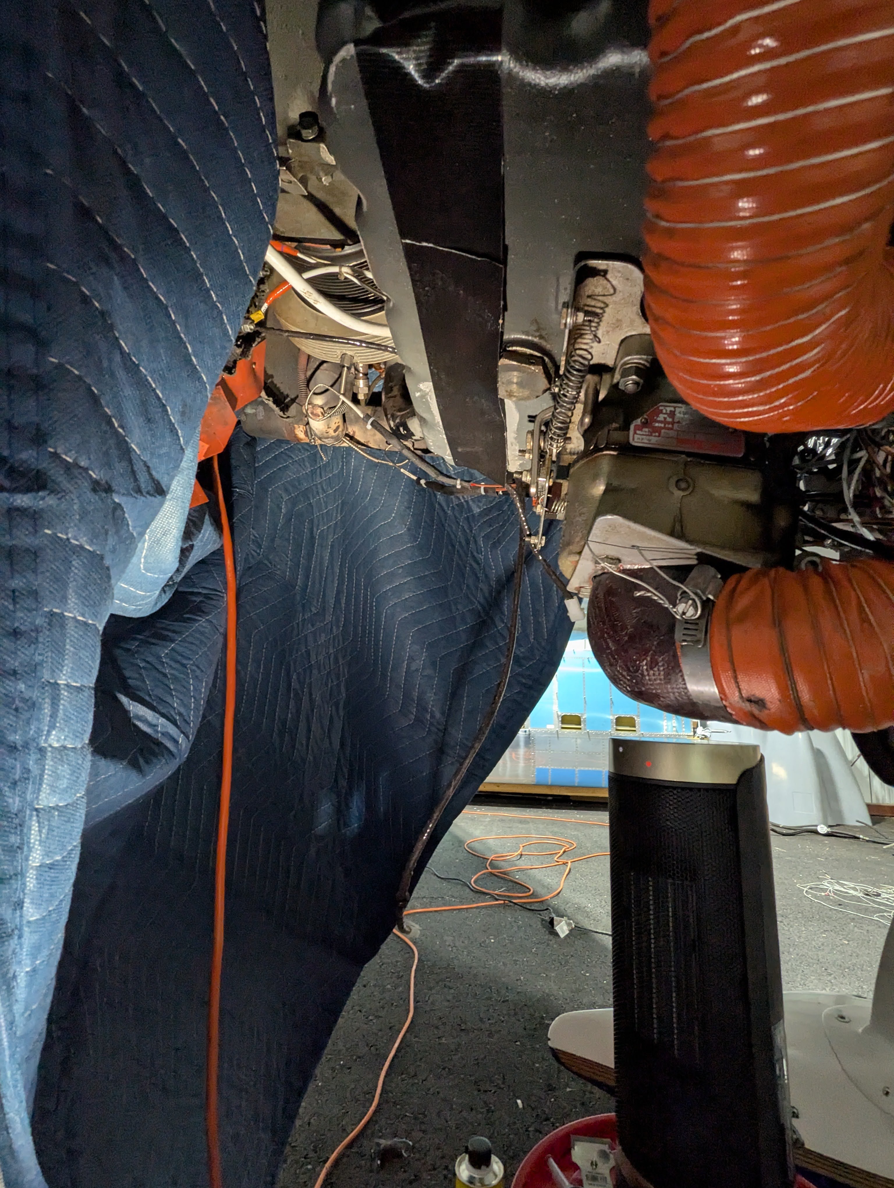
Once I moved into the temporary hangar space, I immediately got to work. I started by removing all of the old equipment. At first I tried to keep the wires that I’d still need intact–things like the master switch, alternator field, electric fuel pump, etc. However, nothing was labeled well and it didn’t take long before I misplaced a wire while pulling it out and lost track of what was what.
Pretty soon I realized it would be best just to pull everything out and start from scratch. I started cutting wires and pulling things out of the plane just to get down to the skeleton. The only electrical component I truly left untouched was the starter. Here’s just a small portion of some of the wire and components I removed.
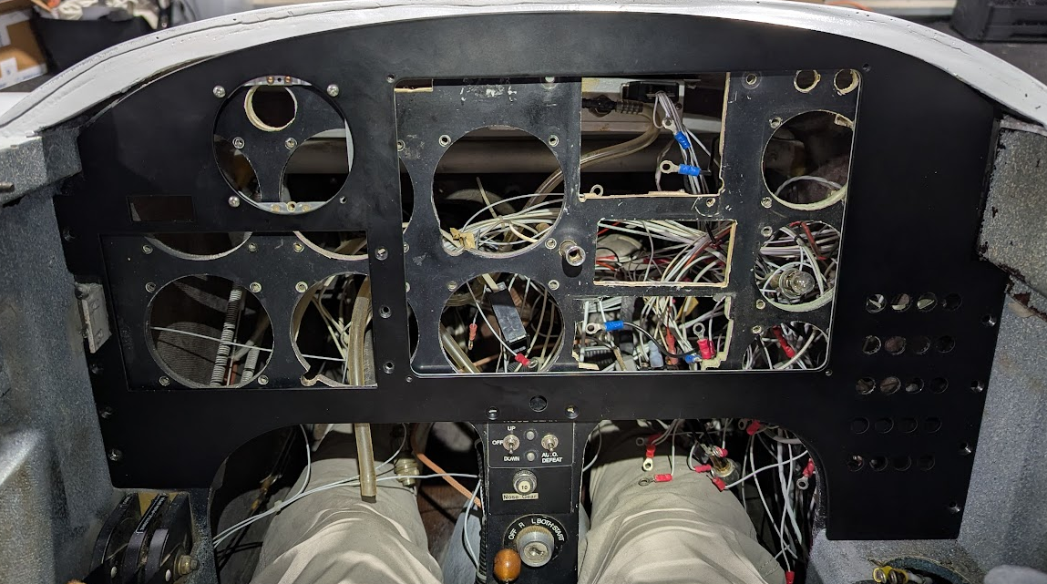
The next step was to remove the panel itself. Since the new equipment I would be putting in had radically different forms and mounting requirements, there wasn’t really any way to make the existing panel and cutouts work for my purpose. This meant the old panel had to go and my new aluminum panel mounted to the remaining structure.
Truth be told, it’s kind of terrifying to use a hacksaw on your plane. At this point I realized I really couldn’t go back, and the only path left was towards completion. When the literal dust settled and I sat back to observe the “damage,” I had a brief thought of “what did I just do??”
I sat in my plane for a bit while I contemplated my choices and observed the fact that I no longer had an instrument panel. However, once I overcame this initial ponderance, I continued forth with the next challenge.
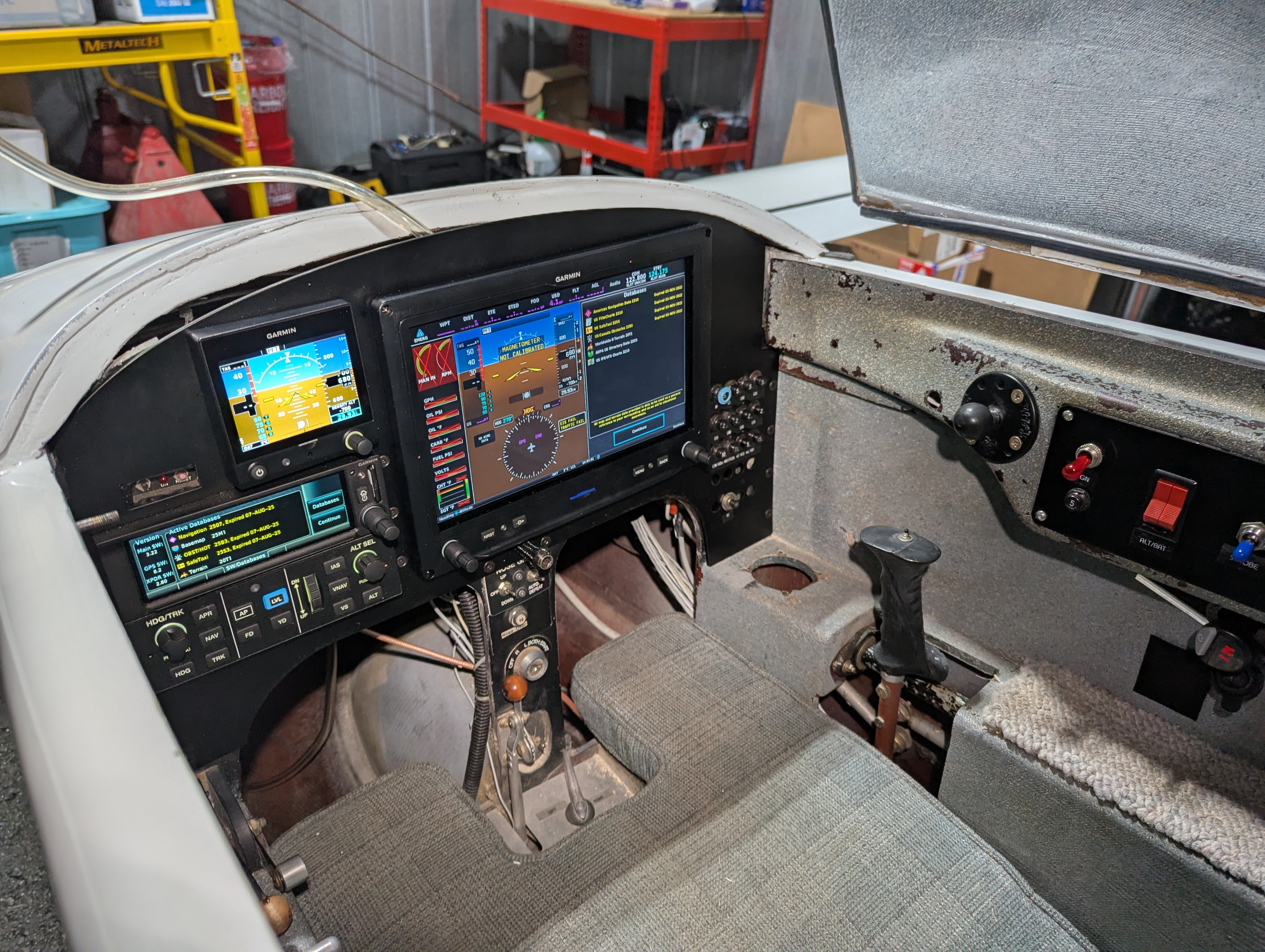
When I worked out my initial plan for everything, part of that included what would become my “stack,” or the assembly of avionics trays that would traditionally hold things like any radios, a transponder, and maybe a GPS or two. In my plane, the stack would consist of my autopilot mode controller, my GPS/transponder combo, and the radio which I would remote mount behind everything.
Originally, my plan was that the radio would sit directly behind the mode controller, and I would leave just enough clearance for the connectors. However, once I was finally able to test fit this plan, which I had fabricated at home based on my CAD drawing and rough measurements, I realized I was short by about an inch of clearance. The issue was that the elevator control on my canard came below the nose a bit further than I had thought, and the connectors on the back of the radio had no room to fit.
It can be a bit of a set back when anything doesn’t go to plan, and in some ways that was discouraging, but part of me just saw this as a new problem to engineer around. I ended up using a combination of aluminum stock from the initial design in addition to a few new parts to come up with a completely new design. This time, I had the advantage of working in situ and there was no excuse to mess up any measurements this time.
It ended up coming together pretty well. I don’t think it’s the most proud I’ll ever be about something I’ve made, but it serves its purpose, and most importantly, it is a solid component that will hold my expensive avionics safely and securely.
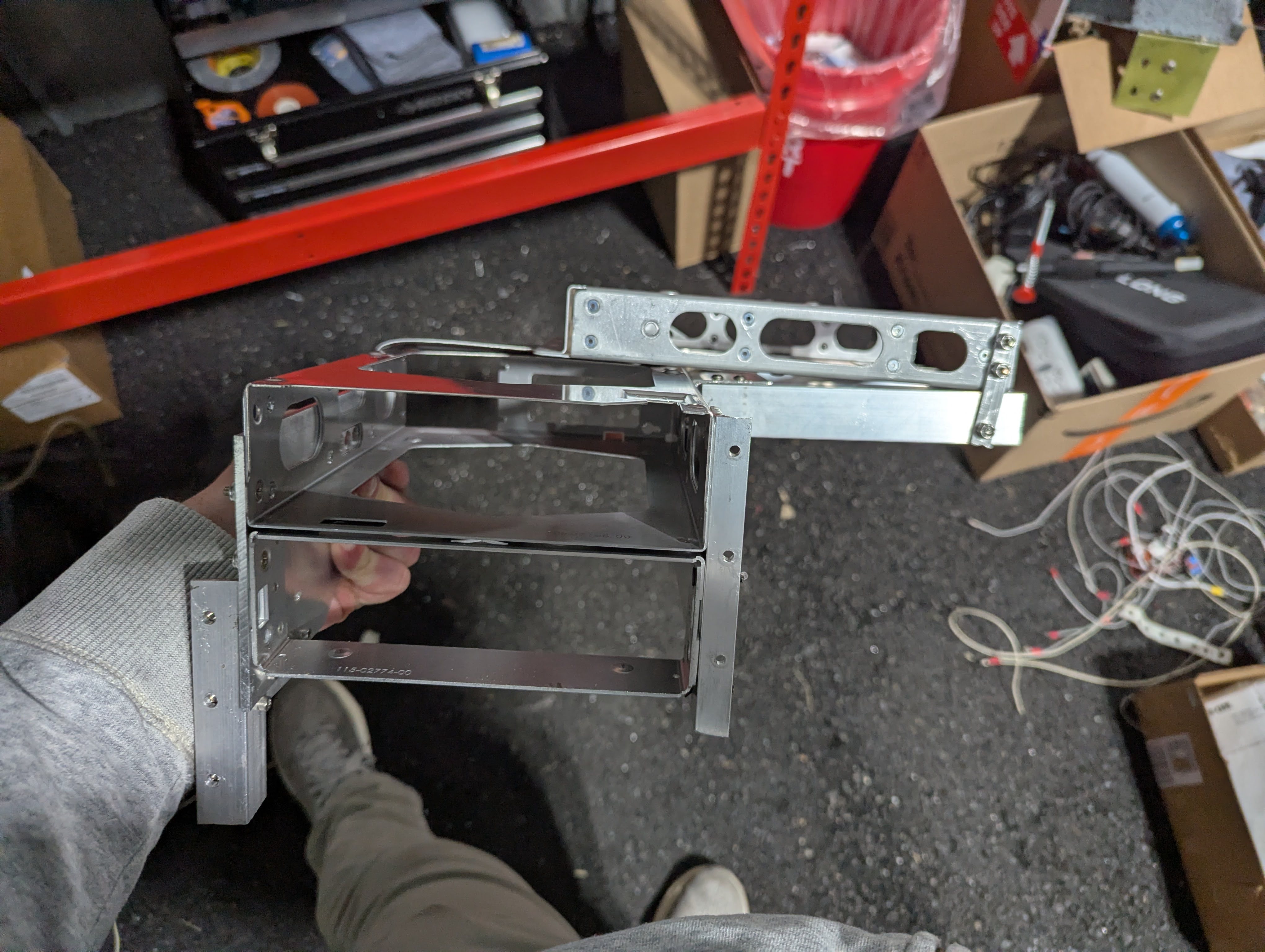
The biggest challenges were working with the constraints of the space as well as the constraints of the harness that I had already made. I ended up placing the radio on top of the GPS/transponder and rotated at an angle to provide clearance for the canard. The only thing I wasn’t super happy with here is that I would need to completely drop the stack from behind the panel in order to remove the radio from the tray. I decided to be okay with this because I figure its a new radio and a new model, and my hope is that I really don’t ever need to replace/service it to begin with. If I end up being wrong, it’ll just take some extra time to get to everything, but it’s not the end of the world.
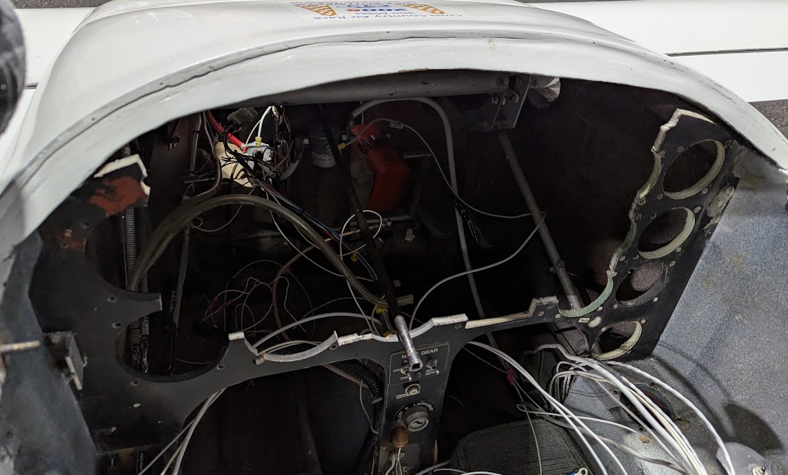
So finally I was able to start putting everything together. The next steps were to physically mount my new panel to the plane, route my wire harness, and start hooking everything back up.
Fortunately, things continued on from here pretty smoothly. I drilled the holes through the bezel I had left on the old panel to line up with the ones machined in the new panel. Then I secured some nut plates to aluminum angle in order to provide additional rigidity and structure to bind my new panel to the plane. Then with a little maneuvering, I could slide the panel into place and secure it. The new panel was a pretty tight fit by design because I wanted it to look good without any gaps as well as be securely held in place.
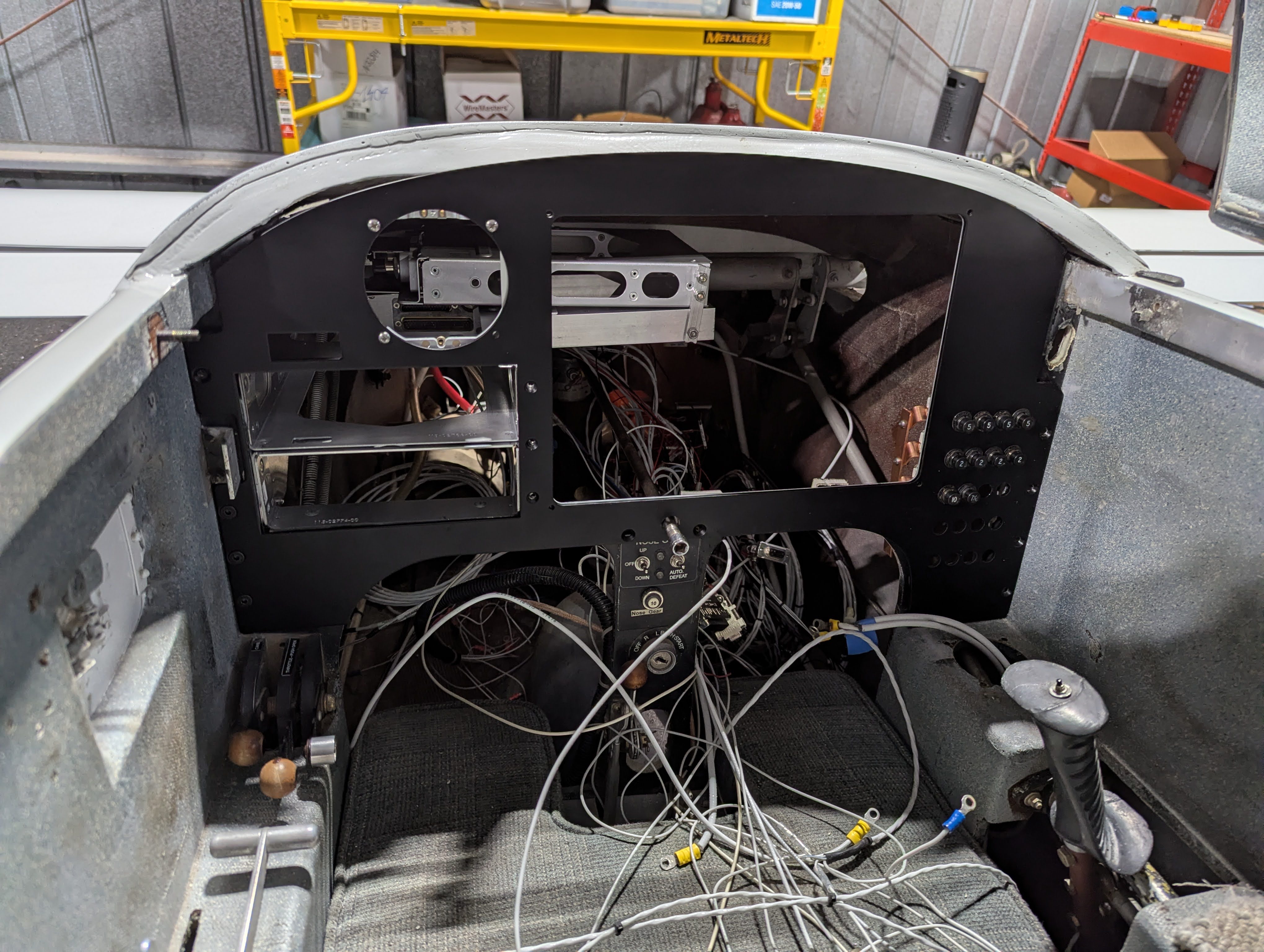
I was pretty happy seeing all this come together now, and I had to take the opportunity to loosely fit my avionics in place. At this point I was still a ways away from turning everything on, but it was motivating to see what my new panel would really look like once I had it in the plane.
The next steps were to finish removing the old wires I didn’t need, install my new wire harness, and hook the harness and power up to the circuit breakers.
In order to finish hooking up the new electrical systems, I had to come up with a new place to mount all the switches. In the previous panel rendition, the builder had come up with a clever side panel that located most of the switches and breakers above my right arm on what I refer to as the “switch panel.”
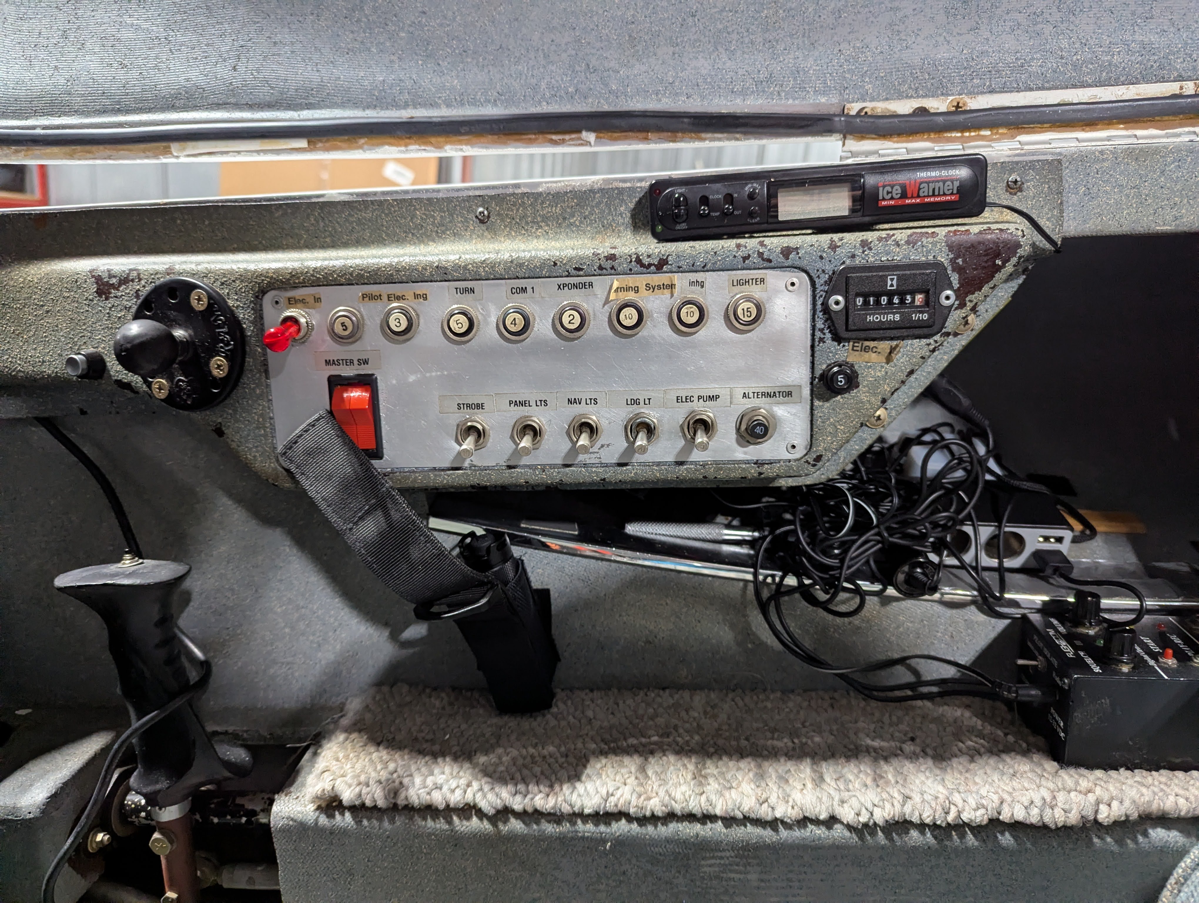
I liked this system, and I wanted to keep it rather than put all of these controls on the main panel. I felt like this would give me more flexibility for future expansion, and it gave the panel up front a cleaner look. However, most of these breakers were now obviated by my breakers on the main panel, and some of the switches were no longer needed. In addition, I wanted to replace some of the breaker switches with a standalone circuit breaker and switch since breaker switches are generally less reliable. I mocked up a new design in CAD and sent it off to be sheet cut and powder coated. A week or so later I received the panel and had installed it.
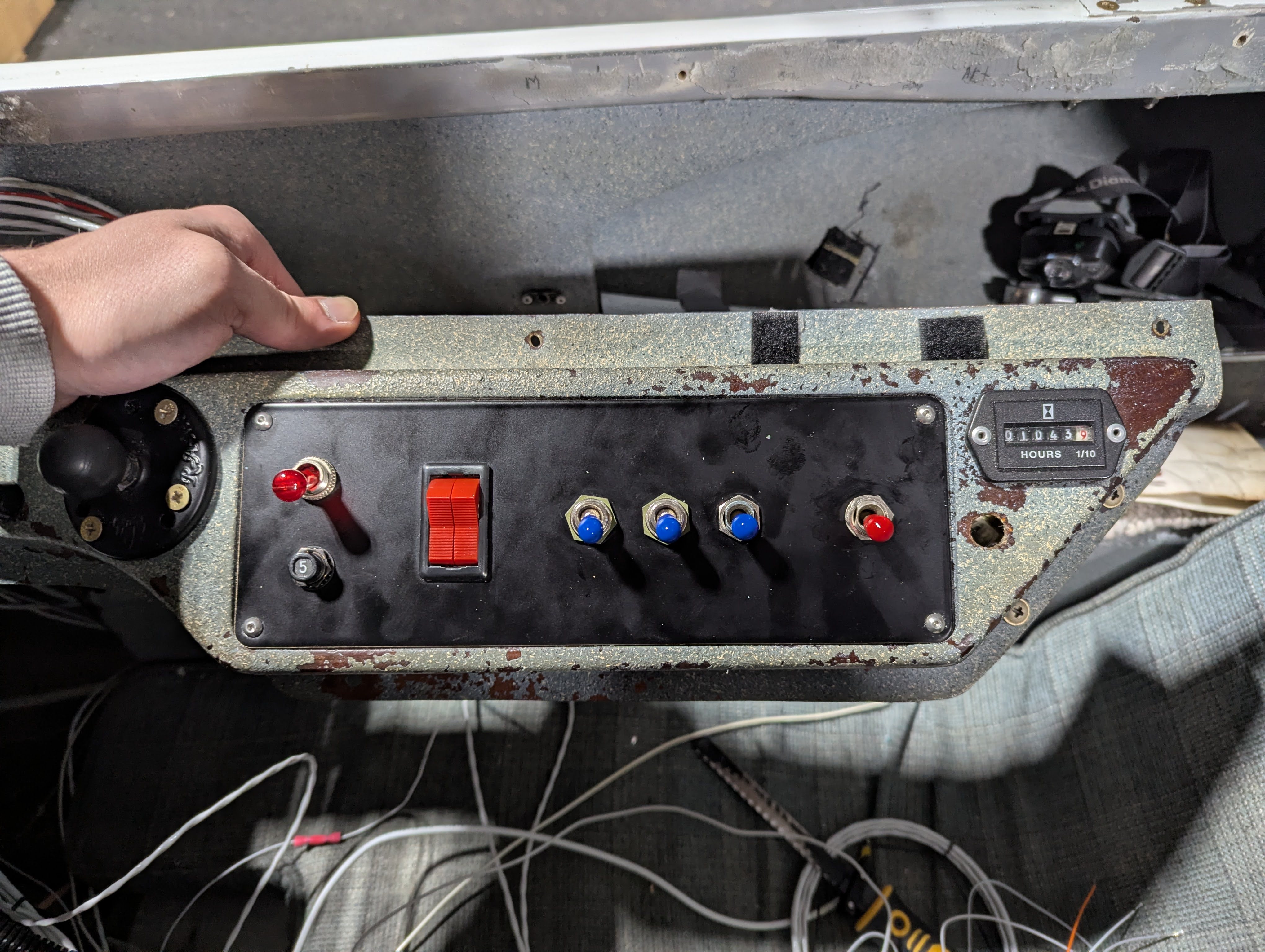
I think this came together really well, and having much fewer items on this panel helps clean it up a lot. I did eventually add labels to these, but from left to right these controls are for the electronic ignition, alternator/battery, strobe light, nav light, landing light, and fuel pump.
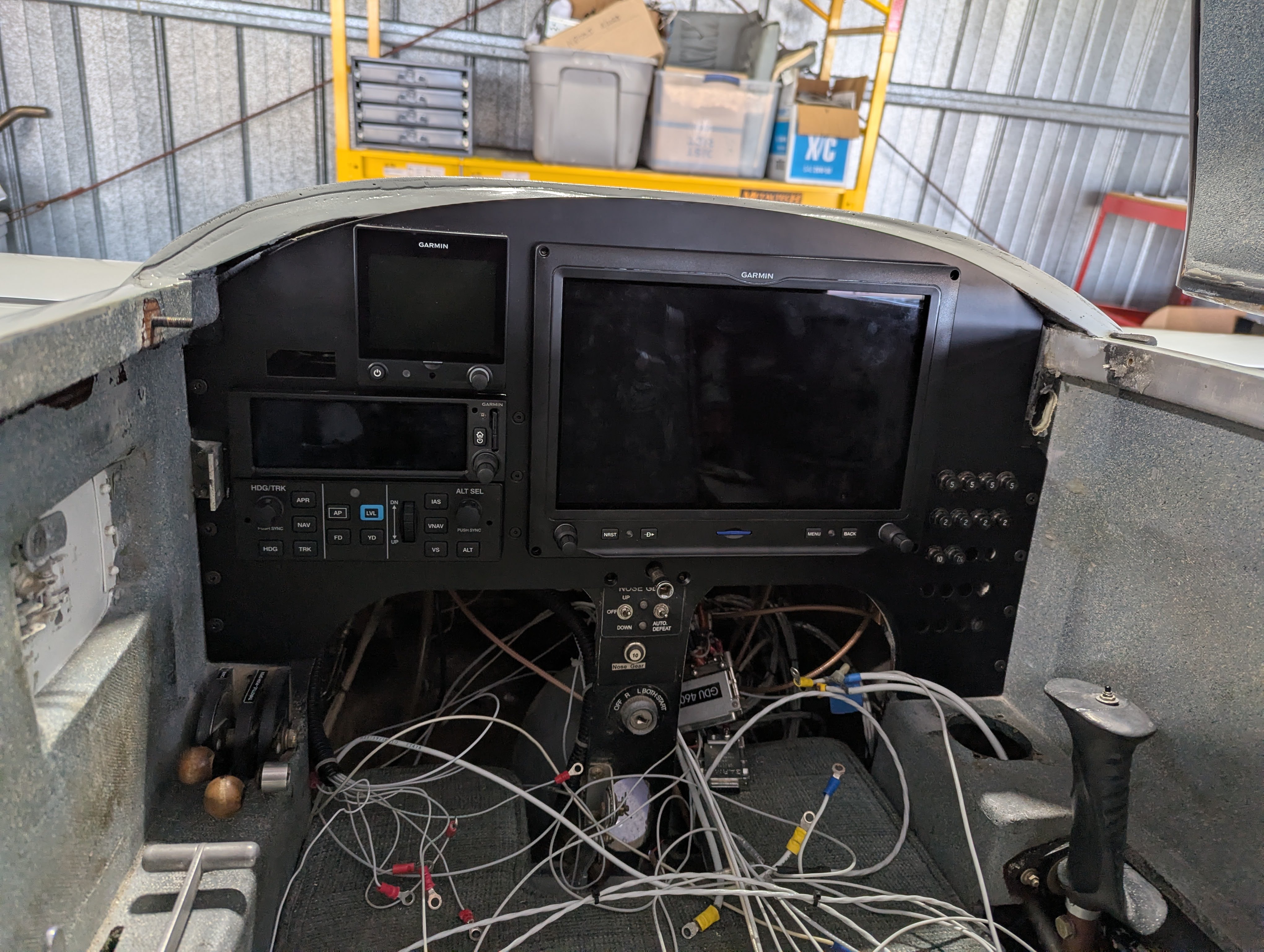
With all the necessary electrical work done, I was finally ready to apply power and see everything light up inside the plane for the first time.
There was still a bit of a ways to go after this, but it was exciting to see everything coming to life. I sat in the plane for a while and played with the avionics, seeing the results of my handiwork. I flipped through all the menus and verified the network statuses of all the avionics were healthy and that I hadn’t damaged the wire harness during the install process. Because I was also hooked up my antenna for the first time, I was able to tune the AWOS frequency and hear the radio come to life and verify my audio wiring was okay.
The next big project moved me towards the aft end of the airplane to work on everything I’d be doing with the engine. First up was one of the most exciting parts of this upgrade, and that was adding a whole suite of engine instrumentation. In the first round of upgrades, I’d be adding just about everything shy of fuel pressure or fuel flow (those will come later).
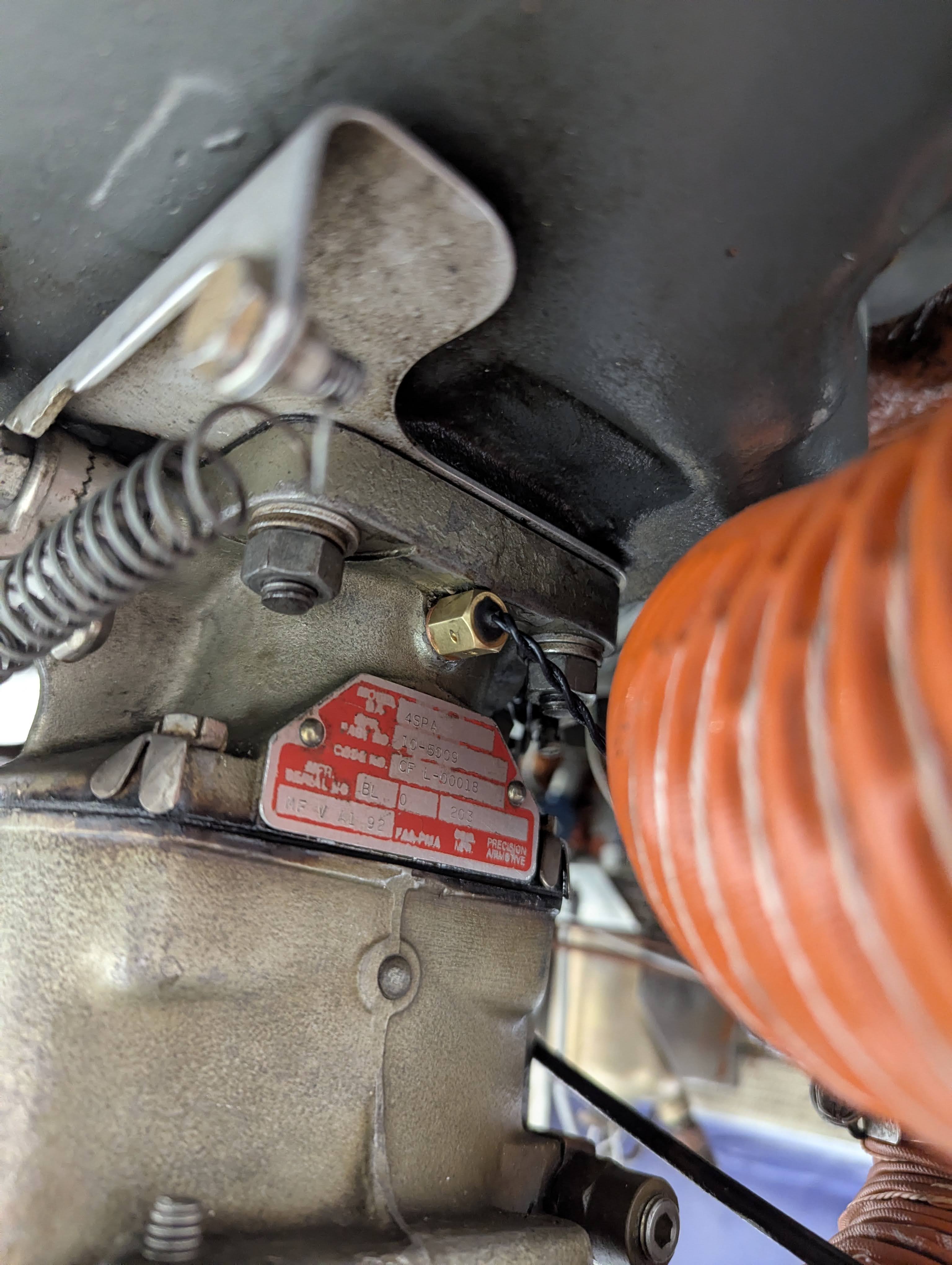
There’s not a ton of interesting pictures from this process. It was a lot of measuring wire lengths, stripping, crimping, securing, etc. All of the sensors pretty much had a threaded port to go into and various compounds to add to the thread such as thread-locker or anti-seize.
Here’s a picture of the carb temperature RTD threaded into the port on the carb.
The complete list of sensors I added in this first round was:
Most of these were replacements for the old sensors that drove the analog gauges, but importantly I did add CHT and EGT probes to all cylinders. Additionally, I was able to wire the manifold pressure output of my electronic ignition as well, and this did not require adding any new sensors. The main bus voltage is provided by using the voltage supplied to the GEA, which is the analog to digital converter that the sensors hook up to.
I wasn’t prepared to mess with the fuel system just yet, so I held off from adding the fuel pressure and fuel flow senders. Both of these are very useful, so it was a high priority upgrade to do later. However, I already did a lot of work on the plane, so I wanted to tackle this a little later to reduce the risk of maintenance induced failures for this first round of upgrades.
Next up, I installed a preheat kit. Having done all of the prior work during the coldest winter months, this was hot on my mind. Not only does engine preheat help get the engine started in the winter, but it helps decrease engine wear. Starting is one of the most wear inducing events an aircraft engine experiences. The engine is made up of dissimilar metals that expand at different rates, so the rapid heating experienced after startup puts a lot of stress on the engine until everything is up to temperature.
I opted to install a Reiff preheat kit. I liked that the clamp style heaters didn’t interfere with any other components, and it ended up being slightly cheaper than a Tanis system. Here’s one of the cylinder heating elements. It’s a clamp with a heating element that goes around the base of the cylinder.
Part of the preheat kit also includes an oil pan heater. This has to get epoxied to the bottom of the oil pan. I scraped off the paint and buffed and cleaned the area to give the epoxy a good surface to adhere to. Then I setup a little tent with a moving blanket over the engine and used gorilla tape to hold the heating element in place while I cured the epoxy with a space heater.
Within an hour or two, this heater system is able to get my CHTs above 50°F and oil close to 70°F on most winter days around here. If I left it on overnight, everything would be over 100°F by the morning, which is great for easy starting.
Finally, it was time to tackle to final component of this upgrade, and the most nerve wracking part of this process for me. Replacing the autopilot ended up not being so bad, but connecting anything directly to the flight controls feels like something you’re not supposed to do.
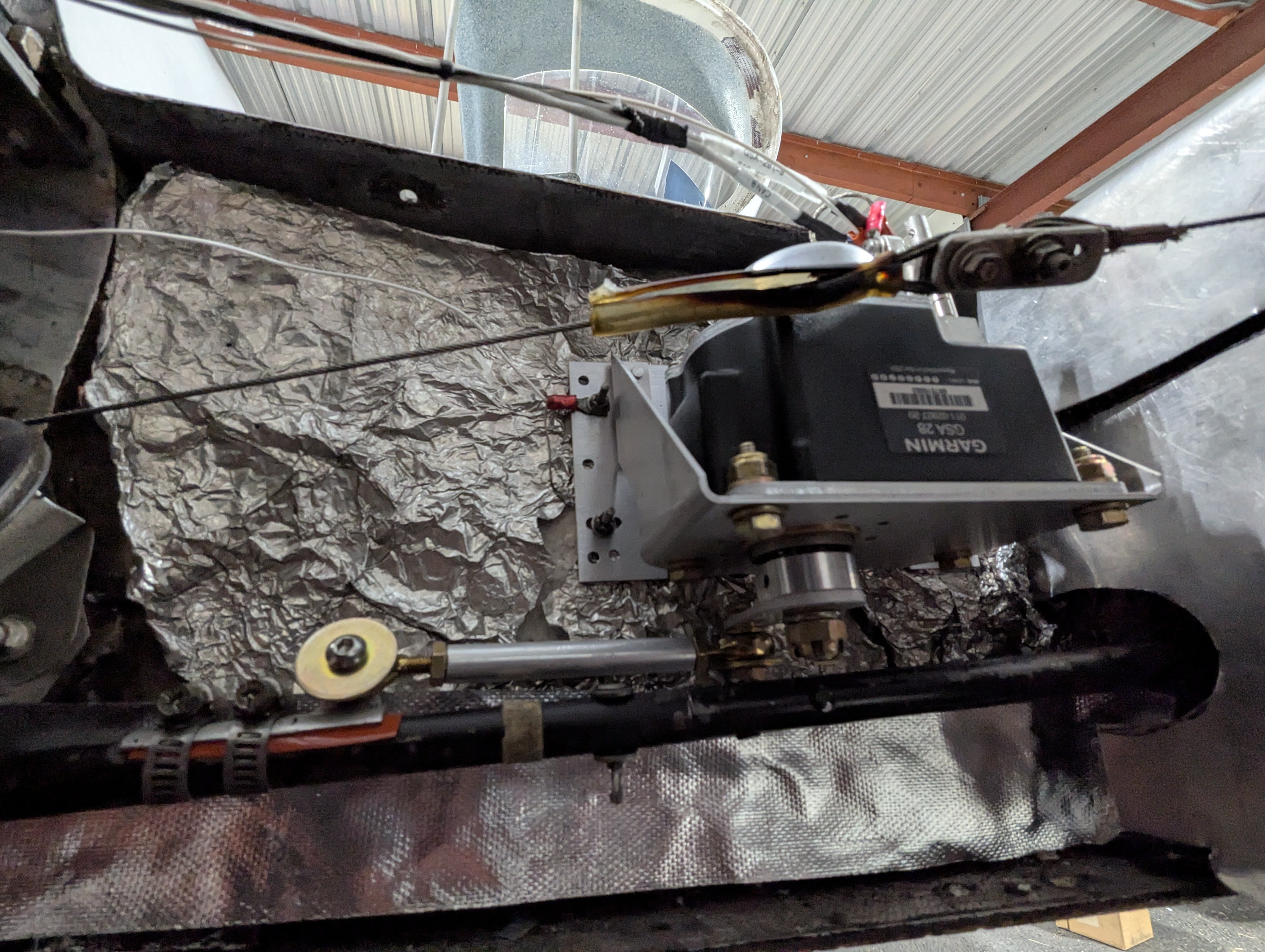
I did have to drill some new holes in the servo bracket to match the hole pattern of the previous servo, but otherwise the install was non eventful. The screws used for the previous servo feel a little undersized to me, so I think I’d like to replace them at some point just for extra security, but I’ll have to work out the best way to do that. For now, it is working well.
The servo has a control horn which connects to a control link. The link is attached to the aileron tube via a clamp system that fits over the tube. I put a thin piece of silicone tape under the clamp to provide extra friction and protect the metals from chafing. I also later added a dab of RTV to the hose clamp screw heads to prevent them from rotating out.
That concludes the last of the upgrades. The final things I had to knock out prior to a test flight were a few calibrations and inspections. The first of which was a magnetometer interference test. This was something I informally did prior to deciding on the placement for my GMU, but so far I had not tested the effects of the engine and alternator on the magnetometer.
The magnetometer is an incredibly sensitive compass that provides the magnetic heading in flight. It must be interference tested to ensure that no equipment on the plane influences the heading, and it must be calibrated to ensure it has a good reference for each cardinal direction.
The interference test involves individually operating every component while watching the readout of the magnetometer and ensuring nothing causes it to exceed its interference limits. At this point I wasn’t quite ready to start the engine, so this interference test would come later, but thankfully the location worked out, and neither the alternator nor the engine caused any issue.
The calibration is a very simple process and involves turning the plane slowly in a circle, ideally over a compass rose where magnetic north is known to some degree of accuracy. The airport I was based at didn’t have a compass rose, so I instead used my phone to verify I was pointed north. Then, I slowly moved the plane in a circle, pausing as directed, until the calibration procedure was complete.
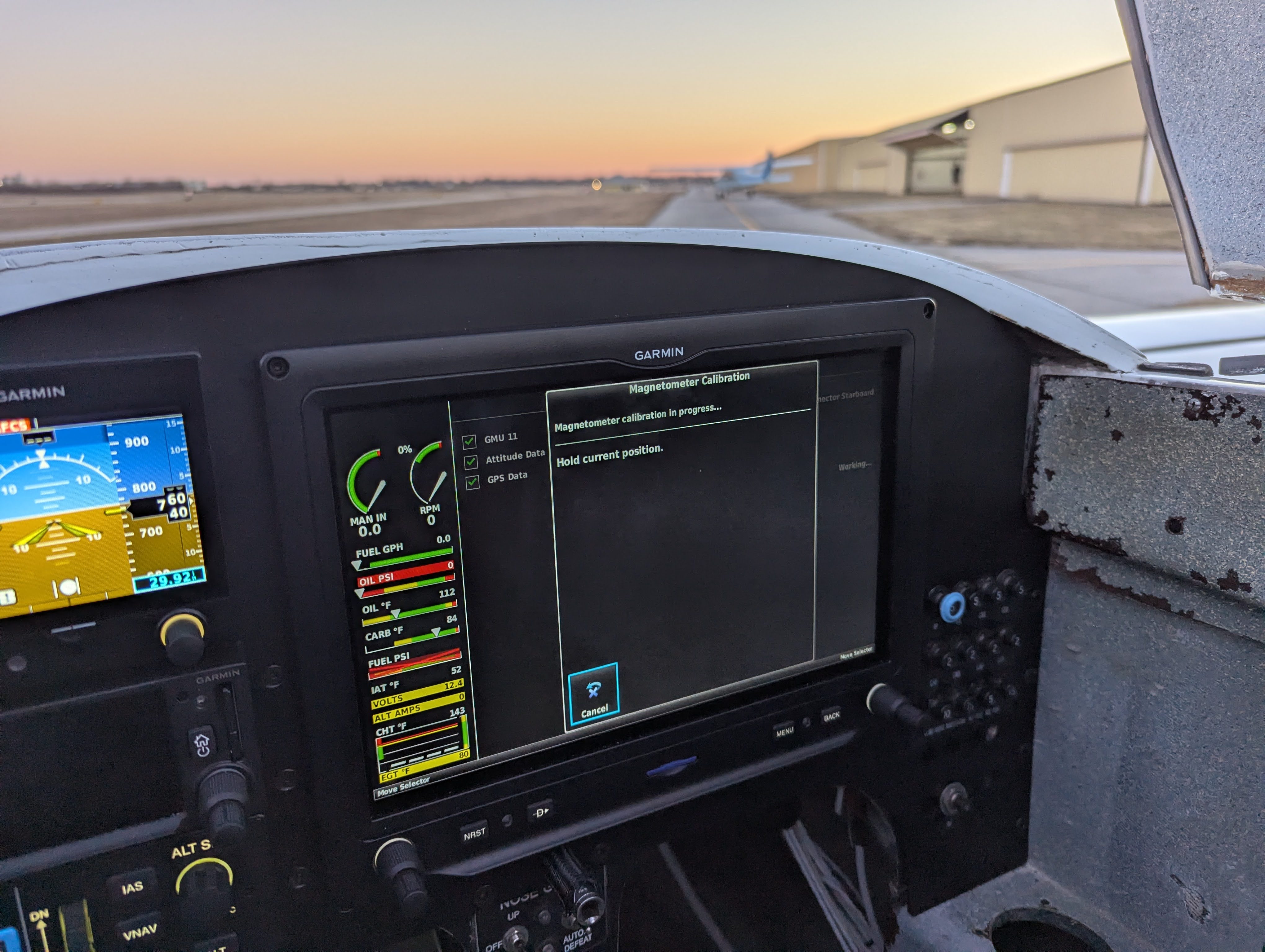
You’re supposed to do this procedure with the engine running, but I opted to do it by pushing the plane instead. With a pusher style engine, ground runs have to be limited to prevent overheating the engine. Additionally, since I wasn’t ready for the first engine start, I figured I’d try it without the engine running first, and if it ended up being a problem, I could always recalibrate it later.
Next, because I put a new transponder in, I had to get it certified. This inspection is required every 2 years and verifies the function of the transponder and that the altitude it reports is accurate. I also now have the capability to fly under instrument flight rules, but this requires another inspection, so I also took the opportunity to get the pitot-static system tested. This is also required every 2 years, but only for IFR operations. This test checks the system for leaks and verifies the accuracy of the air-data instruments. The local avionics shop on the field was able to knock both of these tests out for me in a few hours.
Finally, the last inspection was my own inspection. The plane has spent 2 months in maintenance at this point and has had pretty much the entire electrical system, save the alternator and starter, replaced. Not only did I spend plenty of time on the ground verifying the operation of all my new avionics, but I also thoroughly looked over everything I had worked on.
When I was ready for it, I performed a ground run to verify the new engine sensors all functioned correctly, and the mostly did. The only thing I ended up finding was that the alternator/ammeter was not functioning. Upon later inspection, I found that the plug to the alternator had loosened, probably while I was working on installing the ammeter shunt. I reseated the connector and applied some RTV to hold it in place better. I later realized I had also flipped the ammeter pickup lines, so I swapped those around and the ammeter indication worked as expected.
With everything complete, the time finally came for a test flight. I fortunately had a perfect weather day the next weekend with low winds, low density altitude, and no clouds. I did an especially thorough preflight inspection and started up. Everything went without a hitch. I spent about 2 hours between about five and six thousand feet, circling the airport. The first hour or so was spent monitoring everything to ensure there were no issues, and the second hour I started testing all the systems, particularly the autopilot.
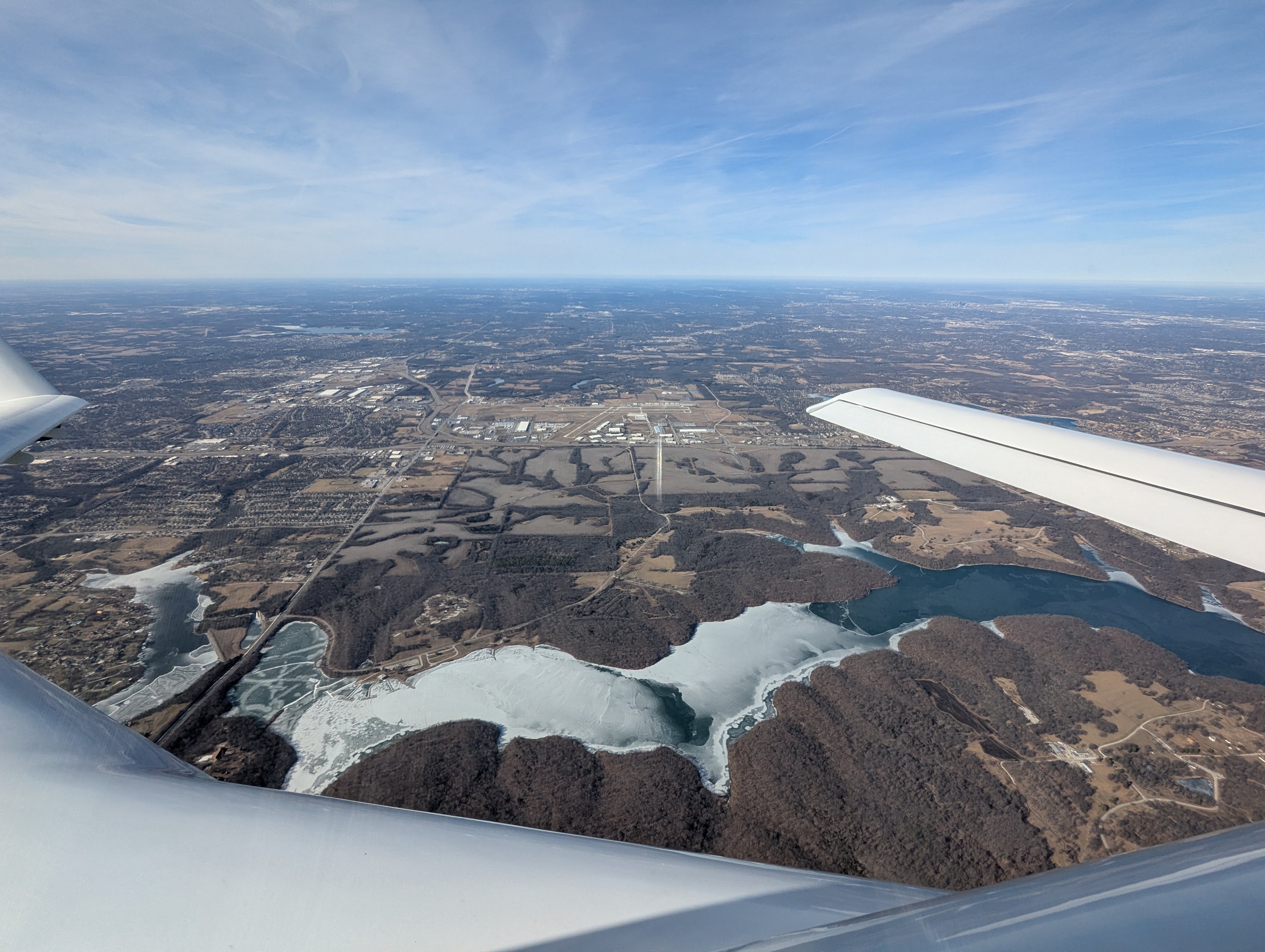
Everything went well, and it was such a rewarding experience to see all of the hard work paying off. The next day I went up to fly again, and with renewed confidence I departed the immediate area of the airport, and flew a lap around the MCI bravo.